:+86 15106109009
:sales@couplingzy.com


 English
 русский
 Español
 عربى
 Português
 Deutsch
 Türk
 Indonesia


Servo Couplers for Mechanical Engineering: Selection Tips and Real Applications
Inhalt
- 1 What Actually Makes a Coupler Suitable for Servo Duty
- 2 Comparing the Coupler Types Engineers Use on Servo Axes
- 3 Where These Couplers Show Up in Mechanical Engineering Applications
- 4 A Practical Selection Checklist
- 5 Installation Details That Decide Whether the Coupler Lasts
- 6 When the Standard Catalogue Doesn't Cover the Axis
A servo axis is an unforgiving piece of engineering. A motor that can reverse direction in milliseconds and hold position to within a few encoder counts will expose every weak point in the drive train, including the component that costs the least. In our experience supplying couplings to machine builders in metallurgy, mining, lifting, port and paper equipment, the coupler is often the last item added to the drawing and the first one blamed when an axis starts to chatter or loses position.
This guide is written from the shop floor rather than from a catalogue. It covers what actually separates a good servo coupler from an average one, how the common types behave in real mechanical engineering applications, and which numbers you should have in hand before you specify anything.
What Actually Makes a Coupler Suitable for Servo Duty
General-purpose couplings are designed to survive. Servo couplings are designed to be transparent — they should transmit motion without adding anything of their own. Five characteristics matter most, and they often pull against each other.
- Zero backlash. Any lost motion between the motor and the load appears as a positioning error the control loop cannot correct, because the loop has no way to know it happened. Friction-fit clamping hubs and one-piece metal elements are used precisely because they have no sliding interfaces.
- Torsional stiffness. A flexible element behaves like a spring in series with the motor. The softer it is, the lower the first resonant frequency of the axis, and the lower the gain you can run before the drive starts to oscillate.
- Low inertia. The coupler's mass moment adds directly to the reflected load. On short, high-acceleration moves, a heavy coupler can consume a noticeable share of the available torque.
- Controlled misalignment capacity. Perfect alignment is a drawing-room assumption. Real assemblies stack up tolerances in bearing bores, housings and mounting faces, so the coupler must absorb parallel offset, angular error and axial float without loading the bearings.
- Balance and speed rating. Above a few thousand rpm, an unbalanced hub becomes a vibration source. Clamp-style hubs with symmetric fastening are easier to balance than keyed hubs with protruding set screws.
Notice what is missing from that list: torque capacity alone. A coupler can be rated for far more torque than the axis will ever see and still be a poor choice, because torque rating says nothing about how the element behaves dynamically.
Comparing the Coupler Types Engineers Use on Servo Axes
The table below is a working summary rather than a specification. It reflects how these families typically behave when they are correctly sized, and it is meant to narrow the field before you open a data sheet.
| Coupler type | Torsional stiffness | Backlash | Misalignment tolerance | Typical servo fit |
|---|---|---|---|---|
| Single diaphragm | Very high | None | Low to moderate | Machine tool feed axes, precise positioning |
| Double diaphragm | High | None | Moderate | Axes with longer shaft spacing or more offset |
| Metal bellows | Very high | None | Moderate | High-speed, high-accuracy drives |
| Jaw / star spider | Moderate | Small, from the insert | Moderate to high | General automation, pumps, conveyors |
| Plum-shaped insert | Moderate | Small | Moderate | Cost-sensitive servo and stepper axes |
| Oldham / cross-slider | Moderate | Minimal with preload | High parallel offset | Encoders, small instrument drives |
| Rigid clamp | Highest | None | None | Rigidly supported, perfectly aligned shafts |
The metal-element families — diaphragm and bellows — win on stiffness and repeatability, which is why they dominate precision positioning. Elastomer families trade a little stiffness and a little backlash for forgiveness and price, which is often the right trade on a conveyor axis that will never be asked to hold a micron.
Where These Couplers Show Up in Mechanical Engineering Applications
Machine tools and precision positioning
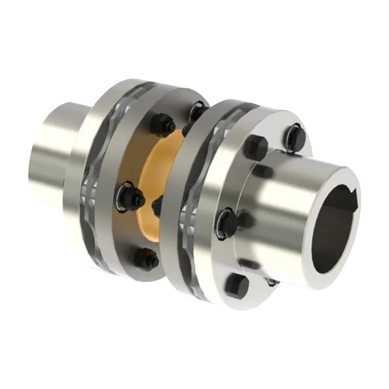
On a ball-screw feed axis, the coupler sits between the motor shaft and the screw end, and its job is to be invisible. A single-diaphragm coupling with clamp hubs is a common answer here: the stainless element is machined from one piece, so there is no relative motion to wear, and the diaphragm pattern can be tuned for the axial float the screw bearing arrangement allows. When the motor and screw cannot be brought close together, a double-diaphragm or intermediate-shaft version takes over.
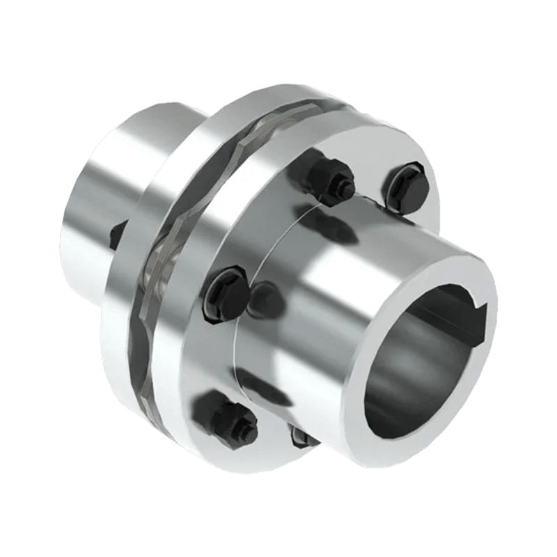 DMA Single-Type Elastic Diaphragm CouplingFor ball-screw feed axes where the coupling should be invisible, this single-diaphragm metal element offers zero-backlash transmission and misalignment compensation.View Product →
Packaging, assembly and small handling axes
These machines run thousands of cycles per shift at moderate accuracy. Star and plum-shaped elastomer couplings are popular because they damp the shock of a fast index and tolerate the alignment you actually get from a bolted frame. The spider insert also gives a controlled failure point: it wears, the axis gets slightly noisy, and maintenance has warning before anything breaks.
 XC Type Star Elastic CouplingFor indexing stations needing shock damping and alignment tolerance, this compact star coupling uses an engineering-plastic spider and supports axial insertion.View Product →
Encoders, tachometers and instrument drives
Small feedback shafts are a special case. Torque is negligible, but parallel offset is common because the encoder bracket is rarely machined to the same tolerance as the main housing. A cross-slider coupling handles that offset with almost no side load on the encoder bearing, which is exactly the load these bearings are least able to survive.
 HJ Type Cross Slider CouplingFor small feedback shafts with parallel offset, this compact cross-slider coupling protects encoder bearings while supporting precise positioning in motion-control systems.View Product →
Heavy plant machinery next door to servo work
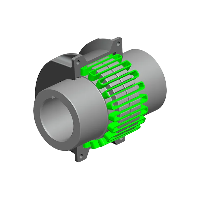
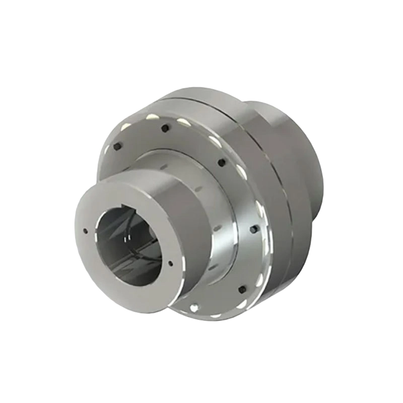
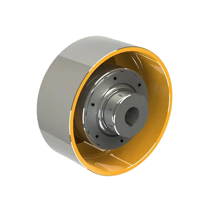
Many mechanical engineering sites run both worlds: a servo-driven indexing station feeding a line, and a crane, mill stand or port handling machine a hundred metres away. The heavy side uses a completely different logic — drum gear couplings, snake spring couplings, and versions with brake wheels or brake discs to suit the hoist arrangement. The design principle is the same, though: match the element to the misalignment and duty, not to the marketing sheet.
A Practical Selection Checklist
Most specification mistakes are not calculation errors, they are missing inputs. Before you compare models, collect the following. It also makes any conversation with a supplier much shorter.
- Continuous torque and peak torque at the coupling, including any gearbox ratio.
- Maximum operating speed, plus any overspeed condition during an emergency stop.
- Both shaft diameters and the tolerance class of each, since clamp hubs are sensitive to shaft tolerance.
- Expected parallel, angular and axial misalignment, taken from the tolerance stack rather than from a guess.
- Available shaft engagement length and the space envelope around the coupling guard.
- Ambient conditions: temperature, coolant spray, dust, washdown, and whether the shaft is electrically isolated.
- Duty cycle, including how often the axis reverses and how fast it accelerates.
If you want a broader view of how the selection logic changes between machine types, our article on how to select the appropriate coupling goes through the same reasoning from a different starting point.
Installation Details That Decide Whether the Coupler Lasts
A correctly chosen coupler can still fail in a month if it is fitted badly. These are the points we raise most often with customers after a service call.
- Align before tightening. Clamp the hubs first, then measure runout at both hubs with a dial indicator, then correct the motor position. Chasing alignment after the element is bolted in place usually means fighting the element.
- Respect the clamp screw torque. Under-torque lets the hub slip on the shaft; over-torque distorts the clamping ring and creates a high spot that shows up as runout.
- Never use the flexible element to pull the shafts together. Diaphragm and bellows elements are stiff axially and will be preloaded permanently if the shaft spacing is wrong.
- Check for axial float. Thermal growth of a ball screw can be a few tenths of a millimetre, which is enough to load a single-diaphragm element if the bearing arrangement is fixed at both ends.
- Inspect on a schedule. Look for fretting dust around the hub, witness marks that show slip, and discolouration of elastomer inserts. These are cheap early warnings.
When the Standard Catalogue Doesn't Cover the Axis
Sooner or later an axis arrives that does not fit the table. A brake disc has to sit between the motor and the gearbox, or the shaft spacing rules out every stock length, or the ambient temperature rules out the standard insert compound. This is where a manufacturer with in-house design and machining capability earns its keep, and it is worth asking how the drawing will be verified — dimensional inspection, material certificates and a balancing report are more useful than a promise.
Our own workshop splits between heavy machining and precision work for exactly this reason, and the details of that setup are summarised on our manufacturing advantage page if you want to see how non-standard couplings are handled from drawing to dispatch.
Servo coupling selection rewards a little patience. Get the torque, speed, bore and misalignment numbers right, choose a metal element where repeatability matters and an elastomer element where forgiveness matters, then install the part with the same care you gave the motor. Do that, and the coupler goes back to being the component nobody talks about — which is exactly what it should be.
- Schnellzugriff
- Über uns
- Produkte
- Unser Service
- Nachrichten & Veranstaltungen
- Kontakt
- Produktserie
- Flexible Kupplungen mit nicht elastischen Elementen
- Flexible Kupplungen mit elastischen Metallelementen
- Flexible Kupplungen mit nichtmetallischen elastischen Elementen
- Sicherheitskupplung
- Starre Kupplung
- Kontaktieren Sie uns
- Tel : +86 511 8572 3800 +86 511 8572 3900
- Mobile : +86 15106109009
- E-Mail : sales@couplingzy.com
- Adresse : Nr. 1 Zhongye Yingbin Avenue, Gaozi Street, Dantu Economic Development Zone, Stadt Zhenjiang, Provinz Jiangsu, China.


